
As this illuminated manuscript shows, motor controllers have been around for a very long time! (Click the image for a larger view.)
Actually, this drawing was made by my friend Mary Lynn Skirvin. It is the schematic for a motor controller from Motorola Application Note AN-445 in 1972. She "illuminated" it as described in the book "A Canticle for Leibowitz" by Walter Miller. In the book, civilization has fallen into a new Dark Age. The monks have been preserving technological knowledge for a future time when mankind will need it again. The copying and recopying led to the same sort of reverent illumination found in documents preserved by European monasteries during the Dark Ages.
As soon as you have a motor, you will want a way to control it. It can be nothing more than an on/off switch, or an incredibly sophisticated and precise motion control system. Here are some example circuits for a few of the controllers I've studied, seen, or even used over the years:


EVs are nothing new; they've been around for well over 100 years! The earliest controllers simply used switches and resistors to directly control motor speed. These photos show the throttle switch and resistor from a very old EV. The throttle pivots an arm that carries a wire with a spring-loaded sliding contact (top). A set of fixed contacts are arranged in a semicircle under it. As the throttle is moved, the sliding contact connects to one or more fixed contacts to select the motor speed. Note the size; the contacts had to be big, because they switch the full motor current and voltage.
Let's look at the switch-resistor controller from a 1902 Baker Electric Runabout. Despite its age, it's actually an effective design. Controllers like this continued to be built well into the 1970's, and can still be found in toys and very simple EVs.
The motor is directly geared to the rear wheels (no clutch or transmission). It is a series motor; a good type for producing high starting torque. A switch selects direction (Forward, Neutral or Reverse) by setting the polarity of the series field. When the series field current flows in the SAME direction as the armature current, the motor runs forward. When the series field current flows in the OPPOSITE direction as the armature, the motor runs in reverse.
The batteries are all wired in series, to provide a 36 volt pack. Switch S1 is the MAIN on/off switch. The speed controller is just a big 4-position rotary switch (S2-S3-S4) and some power resistors (R1-R2-R3).

Resistors R1-R3 are each about 1 ohm, and approximately 12" long and 2" in diameter. Switches S2, S3, and S4 are sequentially closed as the twist-grip throttle is rotated, to provide four speed steps:
The resistors waste power when they are in the circuit. Such a controller is thus inefficient except at FAST speed. SLOW and MEDIUM should only be used briefly to get started. But the Baker has a clever trick to get around this problem. The motor also has a shunt field winding, making it a compound wound motor. When the shunt field is powered by closing BRAKE switch S5, it strengthens the field. This increases motor torque, and also reduces motor speed. This provides a way to drive at lower speeds without the resistors in the circuit and wasting power.
The shunt field provides another benefit; regenerative braking! In HIGH speed with the BRAKE switch on, the motor tries to hold a constant speed, up hill or down. It draws more current going uphill, trying to maintain your speed. It becomes a GENERATOR going downhill, to limit your speed and recharge the batteries in the process.
In fact, the Baker has no mechanical brakes! It depends entirely on electrical braking while driving, and only has a mechanical parking brake to lock the motor when stopped. For greater braking, you switch to REVERSE while going forward. Throttle switches S2-S3-S4 now provide 3 steps of controlled torque in the reverse direction to bring you to a stop. The braking force (and charging current) is quite large with S4 closed; enough to skid the tires on dry pavement.
The design is rounded out by a voltmeter and ammeter, so you can see what the batteries are doing. The ammeter reads in both directions, to show both charging and driving current. The voltmeter has an expanded scale, to cover the range of voltages of interest. Surprisingly, there is no fuse or circuit breaker. Instead, they deliberately undersized the wire in certain places to melt and act like a fuse in case of trouble. A modern version of this controller should include a fuse, or use a circuit breaker for S1.

Due to the confusion possible with so many switches and modes, later EVs combined them all into a single "drum switch". This was a tin can sized cylinder, with copper segments on it for the various switch contacts. Spring-loaded copper "fingers" made the needed connections as the drum was rotated. A single throttle control could then do all the work -- rotate it one way for forward, and the other way for reverse or braking.
This picture is the drum controller in a 1914 Detroit Electric. The Detroit was a very successful and influential EV. Over 13,000 were produced from 1907 to 1939. Advertised range was 80-100 miles with lead-acid, or as much as 200 miles with Edison's nickel-iron batteries (the predecessor of today's nimh cells). A ride in one at a car show in 1976 is what convinced me that EVs could be clean, quiet, efficient, comfortable, elegant, and indeed practical cars.
The Detroit's driving experience was quite different from modern cars. The driver sat in the back seat, with front passengers facing him in the rear-facing "jump" seats to encourage conversation. Instead of a steering wheel, you steered with a long folding tiller in your right hand. Push forward to turn left, pull back for right. Tillers were a common setup back then so there was no steering wheel to get in your way. A shorter lever in your left hand controlled the speed, with five detents for each speed. Lifting the lever up switched the motor into reverse, so you also had five speeds in reverse.
The Detroit's pack was divided into two 42-volt halves, which the controller could connect in series or parallel. It could also connect the twin fields of the 3HP series motor in series or parallel to provide even more speeds. The small spring-like device between two of the "fingers" in the photo is the starting resistor, only used for the lowest speed to start from a dead stop. All other steps are direct connections, for very high efficiency.
The motor was directly connected to the differential, so no clutch or transmission was needed. The controller also provided reverse by swapping the motor's armature leads, so no "reverse" gears were required.
There was no separate "accessory" battery for the lights and horn. Instead, it used 40-volt lights and a bell, powered by one half of the propulsion pack.
Here is the complete schematic for a 1912 Detroit. It even has an ampere-hour counting "fuel gauge" to display range and charging progress, and Tom Edison's nickel-iron batteries for increased range, which was pretty advanced technology for the time.


Big switches can be hard to operate, and their contacts will arc and burn unless they are moved quickly between positions. Later controllers replaced the big switches with much smaller, easier-to-use switches. These small switches controlled contactors (essentially big relays) that moved the big contacts to make the high-power circuit connections.
The picture at left is the contactor controller in a 1960 Henney Kilowatt. The Henney was an influential early EV, and performed quite well given the technology of the time. It was basically a converted Renault Dauphine, with a 7.1 horsepower GE series motor, twelve golf cart batteries, and a rather sophisticated contactor controller. It had a range of up to 60 miles (if driven carefully), and a top speed of 60 mph (with a mile or two running start).
The Henney's pack is divided into four 18-volt modules, with three 6v batteries in each. The accelerator pedal rotates a big cam (top right in the photo). Five microswitches are positioned around the cam. As the accelerator is pressed, the cam sequentially closes from none to all five microswitches. The microswitches control five big contactors (the black rectangular devices in the middle with copper bars screwed to them).
The starting resistor (top left) is only used from a dead stop. It is shorted out by the RS contactor (top left) as soon as the vehicle is moving. The FS contactor (top right) shunts some of the field current away from the motor. This "field weakens" the motor, which lowers its torque but increases its speed. In effect, it acts like shifting a manual transmission to a higher gear. The HI and LO contactors (bottom center) switch the batteries in series/parallel combinations to get 18v, 36v, or 72v for the motor. Note that all batteries are used in all speeds; this keeps the pack balanced so no battery will go dead before the others.
There are three more contactors. The F (Forward) and R (Reverse) contactors (top center in the photo) are controlled by a dash-mounted forward/reverse switch, and connect the motor's series field for forward or reverse. The CH (Charge) contactor is directly controlled by the keyswitch; on to drive, off to charge.
This setup gives the Henney five motor speeds, and electrical reverse. A simplified circuit diagram is shown at right. All switches and contactors are drawn in their "off" positions, and with the accelerator pedal fully released. Red shows current flows. Note that the LO contactors are wired to the normally-closed contact of the LO microswitch; so they are normally on, and turn off when the cam operates the LO microswitch. Click the links to show switch and contactor positions for each step:
This might seem pretty "steppy", but the Henney also has a 3-speed transmission and so was in fact quite drivable (especially for people that drive like the accelerator pedal is an on/off switch anyway).
The Henney is notable as one of the first "solid-state" EV controllers. It doesn't use transistors; but it does use five big diodes (D1-D5). Each diode replaces a contactor contact. Diodes are smaller, lighter, cheaper, more reliable, and reduce the number of contactors that would otherwise be needed. This design came to be known as the "rectactor" circuit (half rectifier diodes, half contactors). It's an effective way to switch batteries (or motors) in series/parallel combinations without an excessive number of contactors. However, the diodes have about a 1 volt drop, and get hot. In the Henney, they are mounted on metal heatsink plates behind the main controller panel.
The complete schematic shows some of the safety features: There are fuses for each 18v battery module, the charger, and 12v power for the microswitches and contactor coils. Extra microswitches are mounted on several of the contactors as safety interlocks. For example, the Forward contactor can't turn on unless the Reverse contactor is off (and vice versa), and you have to start out in LO before you can switch to HI speed.
Properly done, contactor and rectactor circuits are still a viable way to build simple, low-cost controllers. Contactors can be expensive new, but are easy to find used or surplus. In many cases, lower voltage contactors can be used, because they never see the full pack voltage. In the Henney circuit, no motor contact has the full 72v across it, and at least two contacts have to fail closed to create a runaway motor. Be sure to include fuses and safety interlocks. Terrifying things can happen if a contactor sticks "on" and you don't have any fuses or secondary contacts to break the circuit!

Switches and contactors reigned supreme in EV controllers for over 50 years. Vacuum tube controllers were tried; but tubes had too much voltage drop and too low a current handling capability for most EVs.
Then in the 1960's, a new fangled contraption called the "transistor" appeared. Early power transistors were made with germanium, which likes low voltages and high currents. They were ideal for the EVs of the time, which tended to have low-voltage high-current battery packs. The photo shows two Delco 2N1522 40v 50a germanium power transistors made in 1966, and a GE A70A 100v 100a diode from 1964.
Germanium power transistors have a very low on-state voltage drop (0.25v at 50 amps typical for the ones pictured here). That's good! But they are also easily damaged by high temperatures and high voltages. Their on/off switching frequency is limited to a few KHz, which is slow compared to modern transistors. But this is still much faster than mechanical switches -- and they don't wear out!
This made a new kind of motor speed controller practical, called Pulse Width Modulation (PWM). Power to the motor is switched on/off very quickly, so it responds to the average on-time and not the peaks. 0% on-time is off. 10% on-time makes the motor run at 10% speed, 50% on-time is 50% speed, and 100% on-time is full speed (the same as switching the motor directly to the battery). PWM speed control is stepless and efficient.
The earliest PWM controller is the Buck converter, or "chopper". When the transistor switches on, it connects the battery to the motor. The motor's inductance acts like a flywheel, causing the current to ramp up slowly. When the transistor switches off, the current diverts to a "free wheel" diode across the motor, and ramps back down slowly. Controlling the on/off duty cycle controls the average motor current, and thus motor speed. Since the on/off switching speed was limited to a few KHz by these early transistors, such controllers tend to "whistle while they work".
The schematic is an EV controller from 1968 (Motorola Application Note AN-189). It is designed for a golf cart with a 36v pack, and delivered up to 200 amps. A single transistor big enough to handle that much current was very expensive; so they used nine cheaper mass-produced transistors in parallel (a trick that is still being used today). Notice the impressively large RCD snubber across the transistors.
")
This controller works reasonably well, and could be built with modern parts. Substitute silicon transistors for the nearly-unobtainable germanium transistors. The small ones are easy; for example, a 2N4401 for Q1, Q2, Q5, and Q6, and a TIP42 for Q3 and Q7. Unijunction transistor U4 would be a bit harder to find -- the 2N6027 is a close modern equivalent. Q9-Q17 are the hard part. Modern silicon PNP transistors like the 2N5884 would work, but have a much higher on-state voltage drop. You would need to reduce the value of R24, and use more transistors in parallel to spread out the heat.
A more practical approach is to "complement" the circuit -- Reverse the supply polarity, reverse all the diodes, and replace all PNPs with NPNs and vice versa. The output transistors become NPN, which are much easier to get. In fact, you could use a single large NPN darlington transistor module to replace Q8-Q17, which also eliminates R24 and the emitter balancing resistors R34-R42.
Like many Application Note circuits, this one leaves out a number of "minor details" needed for practical use and safety. Add a fuse in series with the battery. Add a contactor in series with the battery or motor to stop it in case of a "stuck full on" failure in the controller. This could be a pair of reversing contactors, wired to the motor's field. It also lacks protection from overtemperature, undervoltage, and broken potbox wires.
An interesting new power semiconductor came along in the 1970's -- the SCR (Silicon Controlled Rectifier). An SCR is a true on/off switch, with no linear region like transistors. When off, it's an open circuit; it does not conduct current for either polarity voltage. When on, it acts like a normal diode; it passes current in one direction, and blocks current in the other direction. SCRs are relatively inexpensive, and available in stupendous sizes that can switch thousands of amps and thousands of volts. The on-state voltage is low (about 1.5 volts) so they are efficient and produce little heat. They switch in a couple microseconds; much faster than power transistors at the time.
SCRs are easy to turn on; all it takes is a microsecond pulse on the gate of about 1 volt at 100ma. But there's a problem: Once on, it stays on! The gate can no longer turn it off. It will remain on until a) the voltage across it reverses, or b) the current through it falls to zero. That's no problem in an AC circuit -- it will turn off at the next zero-crossing of the AC line. SCRs are therefore widely used in AC powered light dimmers, battery chargers, and motor speed controls.
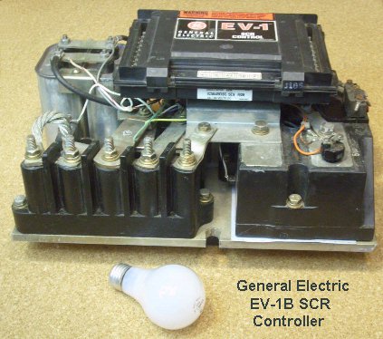
On DC, you need a special commutation circuit to turn the SCR off. One of the most popular of these is the Jones Chopper; a PWM motor controller built with SCRs. This circuit was used in many products, including the famous General Electric EV-1 series of electric vehicle motor controller. Thousands of EV-1's were built, ranging from the little EV-1A for golf cart size vehicles up to the mighty EV-1D that could handle up to 144v and 1000 amps. EV-1 controllers are built like battleships, and very reliable. They were sold from the mid 1970's well into the 1990's, and it's not uncommon to find them still working today (and available on eBay). The photo shows my GE EV-1B, which is set up for 24-84v and 350 amps.
EV-1's were made in hundreds of different configurations, but they all tend to look pretty much like this one. Most are built on a 3/8" to 3/4" thick slab of aluminum called a "panel". The high power parts are encapsulated in massive black bakelite cases, with big bolted terminals. These are wired together with bus bars. You fix these controllers with a wrench, not a soldering iron!
The control logic is on a plug-in PC board, housed in a black plastic box called an "oscillator card" in EV-1 documentation. There are two rows of connectors on top (left pins L1-L10, and right pins R1-R10). These go to external wiring such as power, ground, control switches, etc. Flip the two metal tabs on each side, and the card hinges up to reveal another connector with the wires to the "panel". Unplug this connector, and the card comes off. This makes servicing simple.
There are dozens of different oscillator cards, identified by a 3-character code. The code identifies the card's features and the range of pack voltages it supports. Interestingly, to change the voltage of an EV-1, just install an appropriate oscillator card -- the panel mounted parts are good for any voltage. The cards I know of are:
The oscillator card also has a little door; under it is a row of trimpots to adjust creep speed, current ramp-up rate, current limit, bypass contactor pickup and turn-off points, plug braking, field weakening pickup and dropout.
The EV-1 has the logic and safety interlocks to control the motor's forward, reverse, braking, field weakening, and full-on bypass contactors. However, external power transistors are needed to actually drive the contactor coils (see schematic). Note that the contactor coils must match the pack voltage.
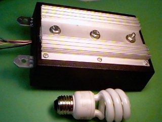
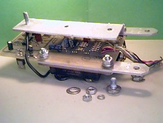
The Petrosonics 500004-1 rev.C motor controller was produced by Petrosonics Inc. of Midland Texas in the mid-1990's. A number of them wound up on the surplus market, which is how I got mine. Since no documentation was provided, I disassembled it and traced out the circuit.
This is a PWM controller for a series or PM DC motor. It's designed for small light EVs like electric bicycles, scooters, and personal mobility vehicles. It is intended for use with a 12v or 24v battery, but all the parts except U2 have a high enough voltage rating for 36v; just replace U2 (LM317T, 40v peak) with an LM317HVT (60v peak).
Motor current limit is adjustable, and can be as high as 300 amps. However, heatinking is very limited, so don't expect to get this much current for more than a matter of seconds before it overheats.
The circuit is simple. No microcomputer; just a quad comparator, MOSFET gate driver, 6 parallel MOSFETs, a big diode, and a big input filter capacitor. If you want to build your own PWM controller, this is a good place to start. It has most of the features you'd find in a higher end controller:
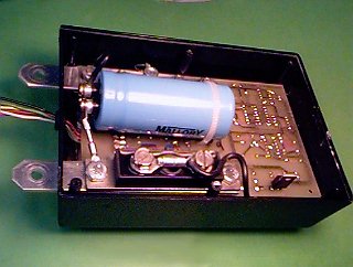
Inside: To open the case, remove the 6 screws from the bottom cover. The left photo shows the view with the bottom cover removed. You can see the large blue input capacitor C0, and 300 amp freewheel diode D1 (the black rectangle at the bottom). LM317T voltage regulator U2 is standing up on the lower right corner of the board.
The battery + and - inputs are 1" wide x 1/8" thick copper bus bars. They are attached to the PC board with screws. Diode D1 uses the positive bus bar as its heatsink.
To remove the board, first remove the nut and ring terminal from the center screw on the "NEG" bus bar. This is one end of resistor R0 on the schematic, labelled point "C". Now flip it over, and remove the 3 large bolts from the heatsink. The board assembly can now be wiggled up, and tilted enough so the bus bars will slide out of their slots in the plastic case.
The right photo shows the top side of the circuit board. Six power MOSFETs Q1-Q6 are standing up, and are screwed to one side a piece of 1" x 1" x 1/8" thick aluminum angle. The other side of this angle attaches to the small heatsink on the outside of the case with three bolts. The motor negative lead connects to this heatsink.
The controller is set up to use a 7-position rotary switch SW0 as its throttle. Minimum resistance is maximum speed, and open is off. You can also use a standard 2-wire 5K ohm throttle pot (potentiometer), connected between P1 pins 1-7. But with a pot, it may not completely shut off at maximum resistance. You can change the value of R20 so maximum resistance on your pot is "off". Or, use a potbox with an "off" switch to open the pot connection.
This controller lacks a safety shutdown in case of an open or shorted throttle pot, and has no undervoltage shutdown in case of low pack voltage. Like many inexpensive controllers, it also requires that you add your own fuse or circuit breaker, and a main contactor with precharge resistor. A potbox switch is a good idea anyway with this controller. It should turn off your main contactor, so the motor will stop even if the controller fails.

Curtis Instruments was founded in 1960, and became a leading producer of EV motor controllers. They pioneered the use of MOSFETs, which are cheaper, quieter, and simpler than the bipolar transistors and SCRs used in other designs at the time. Their controllers have been widely used in both industrial and hobby on-road EVs.
The Curtis 1209-1231 series of DC motor controllers became the industry standard for home-built EVs. They are easy to use, efficient, reliable, waterproof, and have many of the features needed for safe operation.
These controllers are not microprocessor-based, and use common through-hole parts and technology. That makes them more understandable and fixable than most modern "black box" controllers. Otmar Ebenhoech, Rich Rudman, and I have reverse-engineered them so we can all see how they work. A link to the schematic is posted below.
I've used these controllers myself in a number of EVs. Here is the wiring diagram for a typical EV using a Curtis controller. It was a Ford Ranger pickup EV conversion, using a 132-volt pack of 22 6v lead-acid golf cart batteries, Advanced DC FB1-4001 9" series DC motor, and Curtis 1231C-8601 controller.

There are a number of safety features worth explaining. DC EVs can not only fail "off"; they can also fail "on", which means you can't STOP it! EVs last a long time, and like anything else, they tend to get used until something fails. You don't want that failure to be a catastrophe!
Motor Controllers © 2006-2026 by Lee A. Hart. Created 12/5/2013. Last update 4/11/2026.
Go to TOP ........
Go to HOME ........ Questions?
Comments? Email me for details.
Web hosting provided by my good friend and brilliant computerist Jon "Sheer" Pullen.