

Welcome! This website has a split personality (a bit like me). First, it is devoted to my fascination with early microcomputers. I was there at the beginning of the microcomputer revolution. I remember when you could build your own computer from scratch, and program it yourself to do what you wanted it to do. It was a time when computers were simple enough so you could fully understand how they worked. Computers then were truly personal, and not a marketing trap controlled by corporate giants.
Now you can experience the thrill of these remarkable early systems. I offer a number of "Membership Card" microcomputer retro-kits. Each is a complete working computer that fits in an Altoids candy tin. There's one for the Intel 8080, the Zilog Z80, the RCA 1802; and others in development for the MOS Technology 6502 and Motorola 6800 and 6809. Plus a number of other unique hobby ElectroniKits.

Second, this website is devoted to my life-long interest in Electric Vehicles. Even though EVs were invented before ICEs, they wound up in second place. The clean, silent, reliable EVs weren't able to compete with the cheap, quick, and easy power of the ICEs. But things are changing fast. Global EV sales as a percentage of total vehicle sales have been increasing at a rapid rate: 2.5% in 2019, 4.2% in 2020, 8.3% in 2021, 13% in 2022, 18% in 2023, 20% in 2024, and 22% in 2025. Your next new car may well be an EV!
But the US lags well behind the rest of the world in EV adoption. To switch to EVs, the US auto companies have to re-tool their entire industry, and want to recoup their costs as quickly as possible. They also have a vested interest in producing vehicles "just like ICEs" that are big, heavy, and inefficient. Their EVs thus tend to be expensive and hard to fix.
It doesn't have to be that way. Henry Ford's model T and the VW beetle showed that there is a huge market for simple, affordable cars. Europe and China both have dozens of inexpensive EV models to choose from. EVs are intrinsically simpler and cheaper than ICEs! The 1970's CitiCar EV was dirt-simple and the cheapest car in America. Thousands were sold (a record not broken until the Tesla EVs).
The Sunrise Project began with a group of EV enthusiasts to create an affordable, high performance electric kit car that anyone of modest skill can assemble. The Sunrise EV2 is a four-passenger pure electric sports sedan, designed to meet all the safety, performance, and comfort requirements of a modern state-of-the-art automobile.
Finally, there is everything else. I have written many stories, poems, and song lyrics over the years. Some of the more memorable are included here for your perusal and enjoyment.
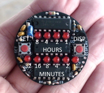
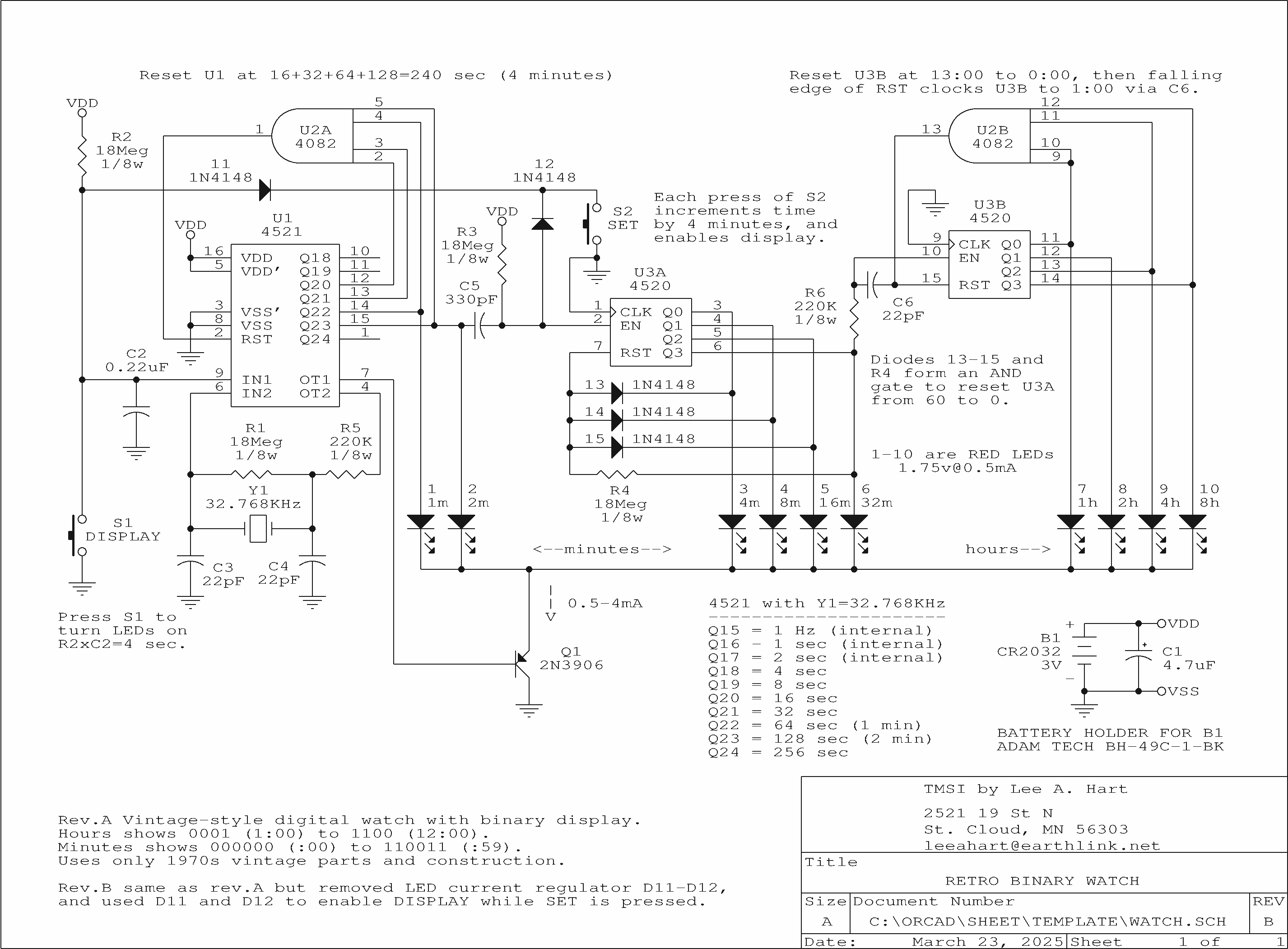
The world's first electronic digital watch was the Hamilton Pulsar. It was introduced in 1970 for the astounding price of $2100 US dollars. The first affordable digital watch was the Sinclair Black watch. It was introduced in 1975 for a mere £24.95 British pounds (or £17.95 in kit form). Typical of Sinclair products, it was brilliantly conceived, but horribly executed.
Both of these alternatives looked unreasonable; so around 1980 I decided to build my own! It worked, but the LEDs at the time were too dim. That's been fixed by modern LEDs, so my 40-year-old project is finished at last.
Documentation
Retro Binary Watch Manual in PDF format.
Watch Schematic in PNG format.

 |
The original Sunrise was designed by Solectria Corp. using the Hypercar principles of Amory Lovins. It achieved remarkable efficiency and range, through the use of lightweight construction, innovative design, and superb aerodynamics. Unfortunately, only a handful were produced.
The Sunrise EV2 project began with the purchase of the last unfinished Sunrise from Solectria CEO James Worden. It is being redesigned as a kit car, along the lines followed by manufacturers of light plane kits for the EAA (Experimental Aircraft Association). The steps are:
Our goal is to make the Sunrise EV2 as modular and open source as possible; like a PC clone, where many different parts can be used, from many different vendors. We'll provide the basic "box". Builders can then use any motor, controller, batteries, charger, interior, and instrumentation they like. Depending on your budget and performance requirements, your Sunrise can be AC or DC, lead-acid or lithium batteries, etc.
We look forward to having a community of Sunrise EV2 builders, where members can exchange ideas, buy/sell/trade parts, and assist others in building their cars. Check this website out occasionally to see how we're doing.
 working on the Sunrise")
Not much progress this past year. Interest in homebuilt EVs really collapsed since the automakers began selling their own EVs. And I've had some financial setbacks that have kept me from investing much more than my own time in the project.
But hope springs eternal. Perhaps the "leadership" in Washington DC will lead to another collapse in US automaker's interest in EVs (as it did in the year 2000). Certainly the US carmakers are going right while everyone else in the world is going left. Maybe there will be a rebirth of interest from people who want to build their own car; one that they can fix themselves without being beholden to Big Auto or the vagries of the government.
There's nobody left to work on the Sunrise EV2 but Igor and I. But, I broke down and bought a gas furnace for the garage. Hopefully we can make some progress over the winter!
In this section, I'll post EV tips and techniques to save you money, find parts, measure performance, and improve your EV. As new ones appear, the old ones will move to the Lee's EVs page. Purchases contribute to the Sunrise EV2 Project. If you like what you see and want me to write more of them, please click the "donate" button below. :-)
If you work with EVs, you need a way to test batteries. I've used all sorts of setups over the years, ranging from jury-rigged parts from my junkbox to sophisticated systems like my Battery Balancer. There are also commercial products, ranging from cheap junk for testing hobby R/C batteries to very expensive professional-grade systems.
I think the most useful ones have been my home-made load testers. They are simple enough to be cheap and easy to build. They are rugged enough to handle high current for long periods of time. Best of all, I know what they are doing, so I know what the test results mean. I've described them before on the EV Discussion List, but here's a more complete description in case you'd like to build your own.
A "load tester" basically consists of the following:
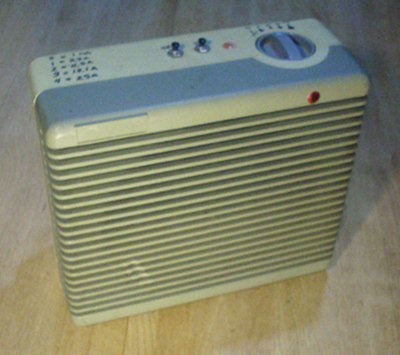
Here's an example: The tester pictured at the right was built in the discarded case from an inexpensive 120vac 1500 watt heater. The case was gutted, and nothing was kept but the fan switch. I installed a 12vdc muffin fan in place of the original 120vac fan. A large aluminum extruded heatsink was mounted in front of the fan. A big 40 amp automotive relay switches the load (the little Fan switch would die trying to switch high current DC). The load was made from a couple dozen surplus 25 watt power resistors in anodized aluminum cases, screwed to the heatsink for cooling. These resistors are wired to the FAN switch so I can select the load current. The FAN switch had 5 positions; Off, Fan, Low, Med, and High. I wired these positions to the resistors to provide the following loads for a 12v battery:
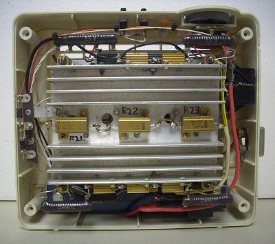
The left picture is the view inside. The heatsink with all the resistors is in the middle. A 4.7" square 12vdc fan is hidden behind it. The CHARGE and DISCHARGE buttons are at the top, and the FAN switch to set the load current is on the top right. The relay is the black box at the right, with a 30 amp circuit breaker just below it in case anything goes wrong.
Voltage is sensed by a modified Manzanita Micro "Rudman Regulator" (barely visible at the bottom of the case). These are normally used to balance or equalize 12v lead-acid batteries. It switches a 7.5 ohm load resistor across the battery if it exceeds a "fully charged" voltage set by a trimpot (i.e. 14.8v). It switches off when the voltage drops about 50 millivolts from this. I modified an old "rev.A" Rudman Regulator to make its turn-off adjustable with a trimpot to a "fully discharged" voltage (i.e. 10.5v). I also added a pair of pushbuttons to manually switch it ON and OFF. The modifications are very simple; only few parts are added.
The relay coil is wired to the regulator's external load terminals. The regulator's 7.5 ohm load resistor was removed (they tend to burn up). The relay contacts switch the battery between the charger and the load resistors. In operation, the regulator switches the battery to the charger until it reaches the "fully charged" voltage; then to the load until it reaches the "fully discharged" voltage; and then repeats.
     ____/\/\/\____________________________________
    |      R27          |  D4      R25             |
    |      1K           | 1N270   100K             |
    O                   |__|/|___/\/\/\__          O
     / S2               |  |\|      ^           S3  /
    O  DISCHARGE        |           |       CHARGE O
 ___|___________________|___________|___________   |
|J1 |                   |           o ___    J2 |  |
| |_|                   |        R5 || R2|    |_|__|
| |                     |      1meg ||___|    | |
|POS    LP1             |___________o        NEG|
|    (removed)                                  |
|               EXT  LOAD                       |
|                J3   J4                        |
|            POS _|   |_     Rudman Regulator   |
|_______________|_|___|_|_______________________|
                |       |
             D5 |__|/|__|
         1N4001 |  |\|  |
                |       |
                |_|_|_|_|
                   K1
       Potter & Brumfield VF4-45F11
     12vdc coil, 40/30a SPDT contacts
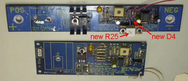
Adjustment: The original trimpot on the Rudman Regulator, R2, works as before. It adjusts the voltage at which the regulator turns on (the high, or fully-charged voltage). New trimpot R25 adjusts the voltage at which the regulator turns off (the low, or fully-discharged voltage). The range of adjustment are as follows (based on my unit):
            Turn-On Voltage         Turn-Off Voltage
R2 at -->  min   center   max      min   center   max
          ------ ------ ------    ------ ------ ------
R25: min  13.38v 14.22v 15.45v     9.85v  9.87v 10.00v
  center  13.38v 14.22v 15.45v    12.88v 13.45v 14.41v
     max  13.39v 14.22v 15.46v    13.13v 13.76v 14.82v
Instrumentation: I used a Cruising Equipment / Heart Interface / Xantrex "E-meter" with RS-232 port, and an old XT PC computer for data logging. A digital multimeter with RS-232 port could serve as well. I wrote a QuickBASIC program to display, print, and save the data to disk. I built this setup over 20 years ago, and still use it regularly!
Click here for my QuickBASIC program to display, graph, print, and log data from the E-meter/Link-10 setup.
Operation: Connect a battery, and a charger. Set up the computer to log the data (or use a clipboard, pencil, clock, and meter). Set the FAN switch for the desired discharge current. Press the CHARGE button. The Rudman regulator thinks the battery has fallen below its lower limit, and turns off. This drops out the relay, which in turn connects the charger to the battery.
The charger charges the battery. When the battery reaches 14.8v (or whatever you set with the original trimpot on the board), the regulator turns on. This pulls in the relay, whose contacts disconnect the charger and connect the load resistors.
The load resistors discharge the battery. When the battery reaches 10.5v (or whatever you set with the new trimpot), the regulator turns off. The relay drops out, which disconnects the load and connects the charger.
The charge-discharge cycle repeats continuously. Or, turn off the FAN switch while charging to end the current cycle with the battery fully charged. Or turn off the charger while discharging to end with the battery fully discharged.
Did you find something on this website that was interesting, educational, or just plain entertaining? Want to get involved? There are several ways you can help.
Contact me: Questions or comments? Corrections or problems with this web site? Contact Lee A. Hart by phone at (320) 224-1054, by email, or by mail at 2521 19th St N, Saint Cloud MN 56303-1377.
Design: Developing products like these requires the skills of many talented people. I'm still learning and improving as I go! If you have ideas for improvements, can help with design, software, construction, or testing; or have other skills you think would be helpful, please contact me!
Construction: I don't offer assembled kits, as it's very labor intensive, and there is only one of me! Do you like to build things? If so, let me know and I can direct people interested in purchasing an assembled kit to you.
Components: Some of the parts in homebuilt EVs and vintage computer kits can be hard to get. If you know of any sources, or have extra parts in your "junk box" that you think would be of use, I may be interested in buying them. Contact me and see!
Donations: Developing projects and maintaining this website costs money. If you'd like to encourage my work, please consider sending a little something with the "Donate" button below. Every penny helps!

The Sunrise EV2 Project, copyright 2007-2026 by Lee A. Hart.
Website created 2/4/2008 by Lee A. Hart. Last update 3/25/2026.
Go to TOP of this page ................ Questions? Comments? Want to help? CONTACT US!
Web hosting provided by my good friend and brilliant computerist Jon "Sheer" Pullen.


