A Lincoln Mark 8 donor car being shortened to the Sunrise EV2 wheelbase. It was used to make a mold of the suspension attachment points and wheel wells for the Sunrise EV2 composite chassis.
What's been done:
|
What's yet to do:
|
Building a vehicle from scratch is a major project. There are endless tradeoffs between cost, performance, and time. Solectria's work gave us a tremendous head start; but many changes were still needed to make the Sunrise into a practical, affordable, high performance automobile.
These are "snapshots" of a work in progress. The design is still evolving. We run into problems, try different ideas, and decide on solutions. You might make different choices; but that is the beauty of a kit car -- you can make changes and build it your own way! And, let us know what you come up with. We might like your way better, and so can improve the design for other builders.
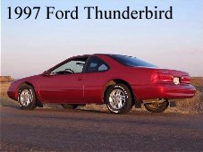
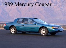
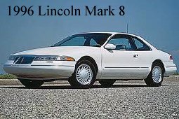
The entire front and rear suspension packages come from a 1989-1997 Ford Thunderbird, Mercury Cougar, or Lincoln Mark VIII. It doesn't matter if the body is dented or rusty, or if the engine or transmission are bad, or if the interior is worn out. These cars can often be bought for a few hundred dollars in damaged or non-running condition. The parts you need are the complete front and rear subframes including brakes, wheels, tires, and steering column; doors, windshield wiper assembly, and all parts related to these assemblies.
Look for models with the V8 or turbocharged V6 engines; they have the preferred Ford 8.8" differential. The Lincolns also have air bag suspension, and aluminum rear suspension arms and differential cases. These parts can save you money and weight.
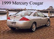
The rear hatch, rear bumper, rear fascia, tail lights, seats, and all related parts come from a 1999-2002 Mercury Cougar. Here are examples of the cars you are looking for:
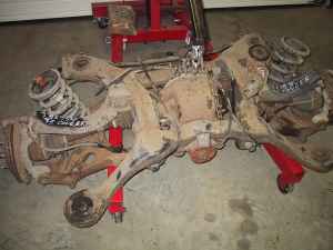
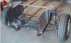
The first step is to pull the rear subframe. It is X-shaped with a large square space in the center for the differential. It attaches to the chassis with four bolts in rubber mounts in the corners. The suspension is fully independent, with upper and lower arms, half shafts, and coil springs on each side (or air bags on the Lincolns). The bottom of the photo is the front of the car. Depending on the year and trim option, it may have disk or drum brakes (with or without ABS); stamped steel, cast iron, or cast aluminum lower arms; and a Ford 7.5" or 8.8" differential.
The 8.8" differential is preferred, as it is stronger and a wider
range of gears are available. The gears are changed to 5.14:1 to
suit our particular motor and controller. The EV2 is rear engined,
so the differential is rotated so the pinion points to the rear.
To do this, a section of the front of the subframe was cut out,
the differential rotated, and the piece welded back in to mount
what used to be the back of the differential in front. Oil lines
were added to convert the differential to dry sump lubrication.
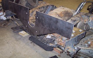
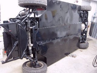
The front subframe is an H-shaped steel stamping, attached with four bolts along each side. The suspension is fully independent, with upper and lower A-arms and coil springs. Note that the steering rack is very low, so the battery tunnel only needs to be elevated about 4" to pass over it.
The photo shows it temporarily mounted to our alignment jig, with
air struts in place of the springs. The inside ends of the upper
A-arms are mounted to fabricated sheet steel supports. These will
eventually become part of the composite chassis.
A temporary alignment jig was built from square steel tubing, to
hold the front and rear subframes in position while the chassis
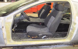
was being constructed. It also allowed us to test fit the body,
seats, steering wheel, etc. to be sure everything worked.
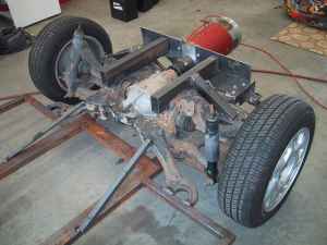
Our goal is to allow any size motor to be used, AC or DC. We used a Netgain WarP 9" series DC motor in our prototype, but there is room for motors up to 14" diameter and 22" long (enough for a WarP 11" if desired).
Toward this end, the motor mounting plate and coupler are made as
simple and generic as possible. The motor mount is fabricated from
flat steel plate. Angle brackets are welded to the ends, which
simply bolt onto the subframe. The brackets also provide mounts
for the anti-sway bar.
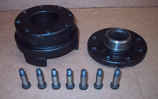
The motor coupler is a standard industrial spider coupling. Very little machining is needed. The part on the right is the stock pinion coupler from the Ford 8.8" differential. It is used as a template to drill the attachment bolt holes in one half of the spider coupler. The other half of the spider coupler is ordered to match the motor, so no machining is needed. A rubber "spider" connects the two.
The slot in the top of the motor plate allows the motor to be
installed or removed from above, by removing the seven bolts and
sliding the coupler apart vertically. This is easier with a long
motor where clearance between it and the rear bumper is limited.
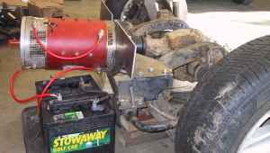
The left photo shows the WarP 9" motor mounted, and spinning the tires. The motor draws about 25 amps at 12 volts spinning the differential and wheels; a very promising number.
We'll be using an external blower for cooling the traction motor.
The WarP motor has an internal fan, but it is not adequate in a
direct drive setup. At low speeds, motor RPM would be too low for
the internal fan to provide enough cooling.
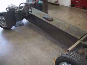
The main structural member in the EV2 is the central battery tunnel. It is a closed box beam, which provides tremendous stiffness and strength. This design originated with the McKee Engineering "Sundancer" EVs of the 1970's, and was further improved upon by high performance EVs including the Solectria Sunrise and GM EV1.
The prototype chassis was built from 16 gauge sheet steel. This
was much easier to work with and modify than composites. It also
allows "early adopters" who prefer working with steel to build
their Sunrise the same way. We went through a lot
of iterations in this process! At least four different rear
chassis designs were built and discarded. It will be converted to
composites once we have confirmed the basic design and dimensions.
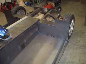
The floor is also constructed from 16 gauge steel. The underside is completely flat, for minimal wind resistance. It weighs about 100 lbs more than the composite version; an acceptable compromise for our "test mule". The chassis is so stiff that it could probably be built with 20 gauge for additional weight savings.
The 4" high space between the elevated front tunnel and the
underside is used as a raceway for wiring, brake lines, and air
ducts. Air flows in the front air intakes, under the battery
tunnel, out under the back seats, through the blower to the
traction motor, and out the rear.
Here is a bottom view of the finished chassis from the front. There will be "trim" panels under the front and rear to improve streamlining over the suspension components.
The backwards "K" shape at the front is a tow bar. It makes it
easier to move the car around in the shop.
While work on the body is being held up, we decided to start making the molds to produce the composite chassis. The metal chassis was only useful as a prototype; you can't make production parts that way.
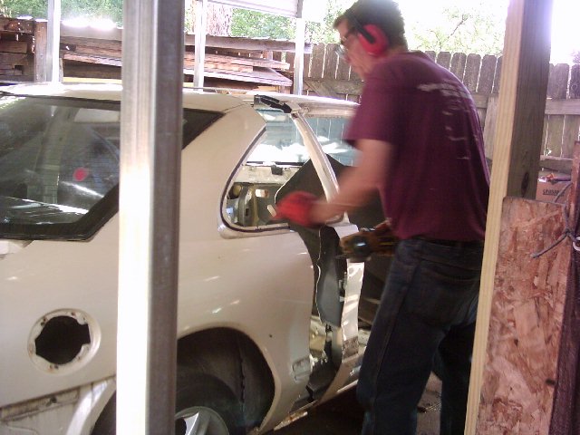
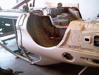
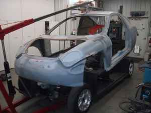
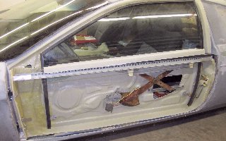
A 1998 Lincoln Mark VIII donor car was purchased, and stripped of its useful components (front and rear subframes, steering, brakes, doors, etc.). It was then cut in half, and shortened 9" to match the wheelbase of the Sunrise EV2. This puts the suspension mounting points in exactly the right positions, so the steel body can be used as a "jig" or fixture to make the mold. The fiberglass mold will be laid up (in sections) on the steel body, to exactly reproduce these critical suspension mounting locations. The body will also provide the wheel wells. The photo shows the body flipped on its roof, to make it easier to work on.
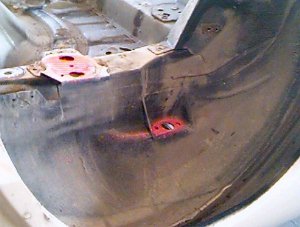
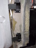
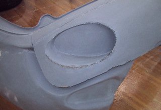
The wheel wells were made first, since we need them for the prototype anyway. The left picture is the "before", showing the rough surface inside the donor car's rear wheel well, with its undercoating, welds, seams, and corrugations in the metal. These all needed to be filled and smoothed.
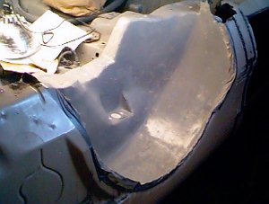
The right picture shows the surface "after" this smoothing. It doesn't have to be perfect, as it won't show. But it does have to be smooth enough for parts to easily release from the mold. A smooth surface also reduces wind resistance. A spinning tire generates a tremendous amount of turbulence. The top of a tire is actually moving forward at twice the speed of the car!
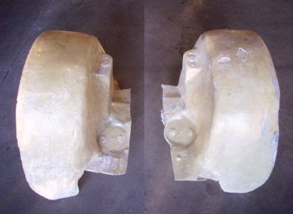
Here is the final result. These first parts are a bit rough, as they were made over the winter, when the cold temperatures here in Minnesota made it difficult to work. I had a devil of a time getting them to release from the mold! But the insides are quite smooth, and they clearly reproduced the important mounting points for the springs, suspension, and shock absorbers.
Next, on to the front wheel wells. It will be the same process: Smooth the inside of the donor car's wheel wells, and make fiberglass molds from them. The molds will be used to make fender wells for the prototype, and become part of the production chassis mold.
Conventional fiberglass car bodies are not structural. They are thick and heavy; but brittle. Most are made with "chopper gun" fiberglass and polyester resin. Or, they are carbon fiber "racing shells" that are only cosmetic; paper thin to be very light, but mechanically very low strength.
In contrast, the Sunrise body is structural; it adds considerably to the strength of the vehicle. The photo shows the opening cut for the rear hatch. You can see the lightweight foam core, varying between 1/4" and 2" thick, with a thin skin of fiberglass, carbon fiber, and kevlar cloth and epoxy resin. The different materials and thicknesses are used depending on the strength needed in each location. The resulting body only weighs about 250 lbs.
The Solectria body is complex, and required a very complicated many-part mold. It had deep depressions for the headlights, taillights, and door hinge pockets. To make these, you need a removable part of the mold with a matching "bump" that can be pulled straight out after the resin cures. But epoxy resin is tenacious; it can be next to impossible to pull the mold out of these deep recesses.
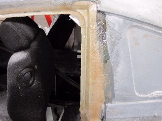
We had to remove these deep depressions, or the cost of molding the body would be tremendous. The leftmost photo shows the original pocket in the A-pillar for the hinges, which was over 3" deep. We filled it in flush as shown in the second photo, so a simple mold can pull straight out the side.
This required new hinges; we couldn't use Solectria's or the ones from the T'Bird/Cougar doors. The second photo shows our hinges. They mount on the surface, but recess the hinge pin in a box to put it at the correct depth. The pillar can now be molded flat, and the hole cut for the hinge later.
The door and hinges in this photo are early light-duty ones made to hang Solectria's doors. Stronger versions will be used for our doors.
Again, you can see the internal construction of the body. The foam core is much thicker, and there are more layers of cloth and resin here, since the A-pillar needs to be very strong.
Here, the body is being lowered onto the test mule's chassis for a test fitting. Ultimately, this chassis and body will be used to make the molds for production parts. But they are also solid enough to install the batteries and controller so it can actually be driven.
A problem presented itself: Like the GM EV1, the Sunrise had a significantly narrower rear track to lower wind resistance. But normal cars (like our T'bird donor) have essentially the same track front and rear. The stock T'bird rear end was too wide to fit inside the Sunrise rear fenders!
We tried narrowing the rear track. Factory Five does this when they use T'bird rear ends in their kit cars. This proved to be too expensive and complicated. We decided to retain the T'bird rear track, so the rear subframe and suspension can be used as-is. That meant moving the rear fenders out.
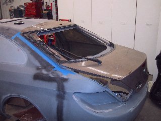
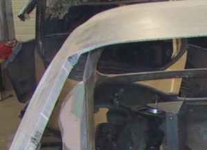
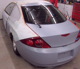
We also wanted to find a glass window to replace Solectria's plastic back window. After many "hunting expeditions" in local junkyards, we found that the rear window of a 1999-2002 Mercury Cougar is an almost perfect fit. Even better, it's a hatchback! This provides far better trunk access than Solectria's narrow trunk lid. We can use the entire hatch, hinges, latch, and weatherstripping as-is. The photo at right shows how closely it matches the Sunrise body lines.
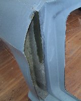
The process for changing the Sunrise body into a hatchback was involved. We removed all the hardware and weatherstripping around the hatch opening in the rear clip. It was then meticulously cleaned and smoothed. Mold release was applied. We then applied epoxy resin and fiberglass cloth to make a "plug mold" of the opening.
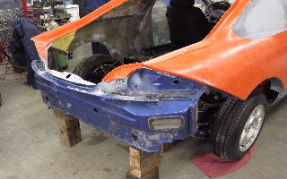
Once cured, the fiberglass part was pulled out. It became the mold to make an exact fiberglass copy of the Cougar's steel body opening. We then cut a big hole in the Sunrise body (sob!), and bonded in the new fiberglass hatch opening. Our new composite parts are orange in the photos.
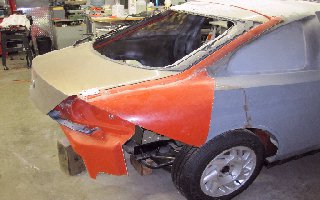
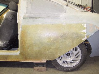
As a bonus, the Cougar has wider rear fenders that will fit the T'bird rear end! We decided to use not only the Cougar hatch, but also its tail lights, rear bumper, and rear fenders as the pattern for our Sunrise EV2 rear end. We bought a Cougar "rear clip" as a convenient source of all these parts.
The new rear fenders were copied from the Cougar the same way as the hatch area. They widen the rear fender wells about 3", and have the correct edges to match the Cougar tail lights and rear bumper fascia.
Rear Bumper
Bumpers are one of the most commonly damaged parts of a car. They also must provide protection in case of a crash. The original Sunrise bumpers were simply part of the molded composite body. While they passed crash testing, the body was destroyed in the process. That would make repairs very difficult and expensive!
We decided to use more conventional replaceable bumpers. The rear bumper is taken from the same car that provides the rear hatch and taillight assemblies; a 1999-2002 Mercury Cougar. This car has an inner steel rear wall, shock absorber assemblies, a hidden composite bumper, and a plastic fascia that provides a decorative cover for streamlining and appearance.
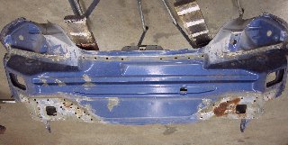
The process for adding these parts to the Sunrise EV2 will give you an idea of the work involved. The first step is to cut out the rear wall from our Cougar rear clip. All edges were trimmed, and the surfaces ground smooth.
The original rear bumper was cut out of our Sunrise body, and the Cougar's steel rear wall temporarily positioned in its place. The steel was trimmed and formed for the best fit.
The orange parts are composite parts made from our molds. The blue part is the steel rear wall from the Cougar.
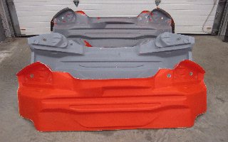
Next, the steel wall is removed, and carefully smoothed, sanded, and painted to provide a very smooth surface so it can be used as a plug mold. Mold release is applied, and fiberglass cloth and resin are laid up on the surface.
When it cures, the fiberglass panel is carefully removed. Now, its surface is painstakingly prepared, so it can act as the mold for our final part. Any imperfections on its surface will be faithfully copied in every part produced, so its finish quality has be very good.
Now we can lay up the fiberglass cloth and resin on the mold. When it cures, we have our first finished composite part. The photo at right shows the steel wall prepped to use as a plug mold on top, the fiberglass mold produced from it in the center, and the final finished part at the bottom.
And here is the finished result! The tail lights and rear fascia have been mounted, so you can see what the new body lines are like. The results are very much like the original Sunrise, but we now have a working rear hatch, glass back window, modern tail lights, and a real bumper that can be easily replaced in case of damage.
Most homebuilts are plagued with "kit car doors" that don't work very well. They leak and rattle, the windows don't roll down, and the latches and hinges are poor. We are determined that the Sunrise EV2 will have real doors that work as well as those on the best production automobiles!
We first tried assembling the doors as Solectria did. While very light, they had fixed plastic windows and fit poorly. Plastics have come a long way, so we tried converting them into roll-down windows with scratch resistant polycarbonate. No good; it was scratched after just 10 up/down cycles.
So, we began the arduous process of designing and building new high quality doors from scratch. Anyone who has done this will tell you it's the hardest part of a car. Gentlemen, you are looking at the result of $30,000 and a year's work!
We used the steel doors from the donor Thunderbird/Cougar as our starting point. The inner door panel was removed, as were all parts for the window, hinges, latch, and mirror. The stripped inner steel panel was prepped, and used as a plug mold to make a fiberglass replica. This was in turn used as a mold to make our own fiberglass inner panel. This provides a lightweight panel of exactly the right shape to mount all of the stock door's parts (photo above).
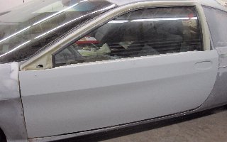
The Sunrise's outer door panel was trimmed to fit the T'bird's inner door panel. New hinges needed to be fabricated, as the stock T'Bird hinges require a deep pocket in the A-pillar, which is impractical to mold in fiberglass. The left photo is with the door skin in place, showing that the resulting body lines perfectly match the original Sunrise.
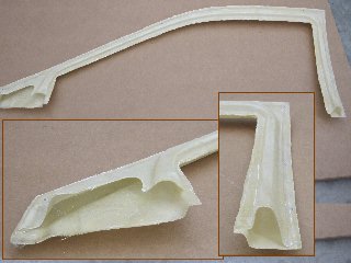
The process was repeated for other sections of the door. The T'Bird's top and side window frame was made from two pieces of steel that formed a box beam for stiffness. These too were copied in fiberglass. The photo at right has three views showing details on the composite window frame.
At last, we have lightweight doors with roll-up windows and latches that work!
The next problem was that the Sunrise body opening is slightly different from the T'bird. This required changing the Sunrise opening to fit the new door. The lower rocker panel needed to move down, the B-pillar had to be moved vertical, and the roofline moved slightly.
The door opening in the body of the donor T'bird provided the pattern for the shape of the door opening to make the weatherstripping work. This required the same laborious process that was used for the rear hatch and doors.
All four sides had to move, and they are all in high-strength areas of the body! Thankfully, we won't have to do this again. Once the prototype body is done, we'll make new production molds from it, which will include these new door openings.
The end result is an exact copy of the Thunderbird's door jamb. It is accurate enough that the Thunderbird's stock door molding fits right on (right photo). That's good, because the T'bird uses double weatherstrips (inner and outer), with a "rain gutter" between them to carry away any water that gets past the outer weatherstrip.
Wheel Openings
Solectria used 13" Geo Metro tires. These are simply too small for a car of this size and weight. We increased the tire size from 13" to 15", in line with modern practices. This required increasing the wheel well sizes and openings.
The top of a tire moves forward at twice the speed of the car itself. Aerodynamic drag is considerably increased if the forward-moving top of the tire collides with the rear-moving air from the car's motion. Fender skirts may be odd looking, but they serve the very useful purpose of keeping these two airflows apart. The result is a significant reduction in wind resistance.
Solectria used removable rear fender skirts to allow tire changes. The Sunrise EV2's air bags allow much more suspension movement, so we chose to make the fender skirts part of the body. To change a tire, just lower the suspension (pump up the air bag). An on-board compressor will make this easy, and also eliminate the need for a jack. Citroen used this method in many of their cars.
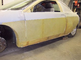
A slanted skirt was designed to match the body lines of the Cougar rear fascia, as seen on the Fioravanti Flair (a highly aerodynamic concept car). The above photo provides a rough idea of the appearance.
The front wheel wells also needed to be enlarged. The right photo is an overall view of the new body lines with the enlarged front and rear wheel openings.
Solectria used Dodge Neon headlights. While serviceable and inexpensive, they gave give the car a dated look, and their lenses turned cloudy faster than any that I've seen. The headlight recesses were also difficult to mold.
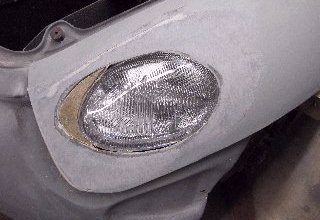
The left photo shows the original opening. The right photo shows what it looks like with a Dodge Neon headlight in place. The fit was surprisingly poor for a car that is supposed to have excellent aerodynamics (notice the filler plate needed below and left of the headlight). One other surprise; Solectria didn't provide any way to adjust the headlights!
We decided to simply fill in the headlight openings. This makes the body easier to mold, and allows builders to pick their own headlight style. A headlight "bucket" will be made to mount inside the fender, and fit the shape of the headlights chosen. A clear lexan cover will then be placed over the headlights for a completely flush surface. This cover can be removed to aim the headlights.
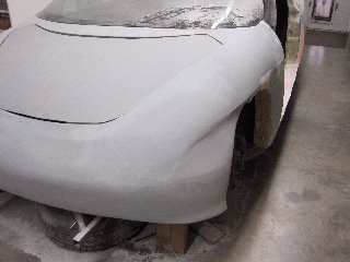
Solectria used Acura front turn signals, which were insanely expensive and provided no styling or aerodynamic benefits. We decided to fill them in as well, so the style can be chosen by the builder to match the headlights. The photo at left shows the front end with both headlight and turn signal openings filled in.

We're now on the lookout for headlights that fit the body shape, are straightforward to mount and adjust, and (hopefully) affordable. So far, the ones from most donor cars are very expensive, or terrible fits for the body lines.
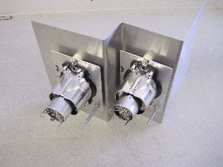
We purchased some generic replacement "penetrator" style lights (see photos at right) to install for now. They are small, easy to mount, not too expensive, and allow many appearance options for the clear plastic cover. They will be mounted in a composite "bucket" to fit inside the front hood/fender assembly.
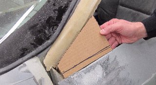
A little "side" problem popped up. Since our doors were copied from the T'Bird, we thought we could use the T'Bird's side view mirrors. But the Sunrise windshield is more steeply raked, so the shape of the triangular area where the mirror mounts is wrong. The cardboard template in the photo shows how steeply slanted this triangular area is (1.5" high at the front, 5" high at the back, and 7.25" in length). The mirror mount area for every car we've looked at is much taller.
Camera/LCD side view mirrors have been suggested. They would certainly be easier to mount, and would be great for aerodynamics as well. Unfortunately, they are not DOT approved, and so are illegal in most places.
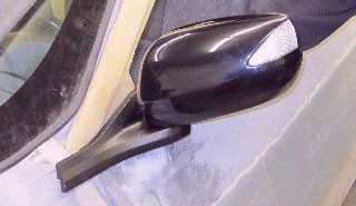
Bill Dennis came to the rescue. He suggested mirrors from a 2010-2012 Honda Insight, and even bought us one to test. It fits! They are power mirrors, with a side marker light, foldable, paintable, and even heated. The factory mirror is expensive, but replacements are available for about $95 each. All that needs to be done is to trim off about 2" at the front where it meets the door line.
 Windshield Wipers
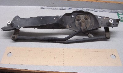
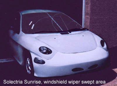
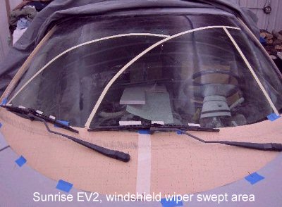
The next task is to work out the windshield wipers. Our plan is to use the wiper mechanism from the T'Bird donor car, which is a nice prepackaged assembly on a lightweight plastic support. This defines the locations of the wiper arms (see right photo). It also provides better coverage than the Solectria wipers, which left a large unswept area on the passenger side. Unfortunately, it also places one of the wiper pivot points in the hood.
The Solectria Sunrise left the wipers exposed. The GM EV1 put them under a raised cowl to reduce wind resistance, like many other modern cars. We opted to do the same, so the wiper pivot point is under the hood and not on it. This requires extending the hood and raising its rear edge about 2" above the windshield.
The cowl considerably increases the size of the hood. This would require a custom articulated hinge mechanism, as found in many cars. So, we are looking into making the hood and front fenders as a single part. It would be hinged at the front to swing open, or could be removed entirely by pulling a couple of pins. This has many benefits: It simplifies molding the body, provides better front end and battery tunnel access, improves streamlining, enhances appearance by eliminating seams, and provides an easy to replace "crash part" in case of accidents.
Now that people can buy a Tesla, Leaf, Bolt, and other automaker-produced EVs, the interest in home-built EVs and conversions seems to have died. Bob Rice, our group's founder and inspiration, has also passed away.
Today's EV buyers seem to be obsessed with range and luxury. The automaker's EV offerings are correspondingly expensive and heavy (even more so than current ICEs). There seems to be little interest in a car with half the energy usage and half the cost.
So one by one, the members of the Sunrise team have drifted off to their own projects. I am continuing to work on the Sunrise EV2, if for no other reason than to prove the concept, and have a hypercar of my own to drive. Who knows... The EV market has always had its boom-and-bust cycles. Perhaps a time will come again when people are interested in truly efficient affordable vehicles, even if they have to build it themselves.
I'll EVing you,
Lee Hart
The Sunrise EV2 Project, © 2007-2022 by Lee A. Hart.
Created: 2/9/2008. Last updated: 11/18/2021.
Go to TOP ........ Go to HOME ........ Questions? Comments? Want
to help? CONTACT US!
Web hosting provided by Innovative Computers.