Battery Balancer
A Powerful, yet Simple System to Monitor, Test, and Balance Batteries
"There are few industries with more BS than the battery industry."
(Elon Musk, Tesla CEO)
by: TMSI c/o Lee Hart
814 8th Ave N
Sartell, MN 56377
3 2 0 - 6 5 6 - 9 5 7 4
The Battery Balancer is a system to keep the battery pack in an electric vehicle balanced (all cells at the same state of charge). While charging, it prevents the first batteries that reach "full" from being overcharged by transferring charge to other batteries that are not yet fully charged. While discharging, it moves charge from the stronger into the weaker/lower capacity batteries in the pack so that all batteries will reach "empty" at the same time. Unlike shunt regulators, it does not waste excess charging energy as heat -- it instead uses a DC/DC converter to efficiently transfer power between batteries as needed. The Battery Balancer can also do advanced testing and measurements, such as amphour capacity, internal resistance, and temperature rise. The Battery Balancer works with individual cells or batteries (groups of cells) from 1.2v to 12v each, of any chemistry (nicad, nimh, lead-acid, or lithium).
I designed the Battery Balancer as a research and development tool for my own EVs and for battery experimentation. It has proven so useful that full documentation, schematics, parts lists, PCBs, and software have been made available to others interested in such a device. You can build it yourself from scratch, buy just the bare boards, parts kits, assembled boards, or complete units. But it is NOT a commercial "plug-and-play"product. It is built by hand, and each one tends to be customized to the particular needs of the user. Think of it as a piece of test equipment, like a multimeter or power supply. It doesn't do the job for you, but it gives you the tools to take measurements and make decisions yourself. You should be willing to accept the challenge of finding parts, assembling the boards, and writing your own software. I can only offer limited technical support.
I have described this system and its evolution many times on the EV Discussion List. Roger Stockton collected many of these discussions and put them on his website at Balancerland. I owe Roger a great debt of gratitude for his work, as I had no idea how to put this information on the web at the time!
Why Balance?
In theory, all batteries are identical. If wired in series, you would therefore expect them all to charge and discharge equally. But in practice, there are differences. New batteries that are all the same brand, same model, same date code (and without "lemons" or quality control defects) will still have small differences. Each cell 's self-discharge rate, amphour capacity, internal resistance, and charge/discharge efficiency will be slightly different. This makes them drift to different states of charge. For example, cells with a higher self-discharge rate run down faster just from sitting. Cells with a lower amphour capacity get more deeply discharged on each cycle, which lowers their efficiency (so they need a bit more current to fully recharge). Cells with a higher internal resistance run a little hotter, which affects their efficiency and self-discharge rate. These differences tend to get larger over time. If not corrected, you can have a pack with some cells almost full, and some almost empty!
The traditional way to correct for these imbalances is to deliberately overcharge the pack slightly (sometimes called "equalization"). The slight overcharging tends to "pound down" the best cells to weaken them a little to match the rest. Then do something to limit discharge to leave about 20% in the pack, so the lowest cell won't fall to 0% (like a gas gauge where "empty" really means you actually have two gallons left). Not running the pack dead avoids destroying the weakest cell that might be at 0% when you thought it was at 20% state of charge. But these are weak "feathers on the scale" correction methods. They only work when the imbalance isn't too large. You can't use the full capacity of the pack. Since overcharging shortens battery life, it also has the drawback of reducing the life of the pack as a means of keeping it in balance. The result? "Buy a new pack every few years."
A Little Background...
I started working on EVs in 1974, due to the Arab Oil Embargo. I converted a Datsun pickup into an EV, with a dozen 6v golf cart batteries in the bed, a surplus aircraft starter/generator as a motor, and a homebuilt contactor controller. I murdered my first set of batteries in about six months, from all the usual causes: Draw too much current, drive until it won't move any more, fail to recharge properly, repeat until dead. It was a clear case of battricide. My only defense was that I didn't know any better!
"Batteries do not die of old age. They are murdered!" -- (Rick Proctor, Cruising Equipment Company CEO)
I found that traditional balancing methods only work when the batteries were fairly new and well matched. As the pack aged, or degraded due to abuse, the differences between batteries got larger. At some point, one of the batteries would fail before the rest. The usual solution was to replace the whole pack. But that's expensive (and I'm cheap). So I'd replace just the bad battery, and keep going.
This worked; but led to new problems. Total pack voltage was no longer a good indication of the state of charge of the pack. During charging, the new battery was more efficient, and so reached "full" well before the others. It would then get seriously overcharged while the charger was trying to bring the whole pack up to its "full" voltage. The new battery thus got "hammered" harder than the rest, shortening its life. During discharge, the total pack voltage would be OK even when the weakest battery was very low. It would thus get too deeply discharged, and so would fail even sooner. These problems are what leads to the conventional wisdom "don't mix batteries".
I set out to "balance" the individual batteries in my mismatched pack, and thus get more range and more life out of them. I measured each battery's voltage individually, and then charged them individually as needed. This prevented overcharging problems from damaging the newest or strongest battery, so its life didn't get reduced. I could also find the weakest battery, and connect a meter to watch its voltage while driving. That kept me from over-discharging it. Sure enough, weak batteries lasted a lot longer if not overloaded or abused. This simple scheme was enough to let me deal with mismatched packs, and keep driving on batteries that were well past their normal end of life.
My first Balancer was therefore nothing but a rotary switch and a meter. I could select each battery one at a time, and check its voltage. I could find the lowest one while driving, so I didn't run it "dead" to damage it. During charging, I could find the first battery that reached "full", and stop the main charger at that point. Then finish by individually charging any that were still low. I could also select any battery, and individually load it or charge it to manually balance the pack. This is still a viable method today. If you do nothing else, at least install switches and meters to let you do this!
Rotary switches (especially with more than 12 positions) are hard to find. Above is a simple Manual Battery Balancer circuit that uses toggle switches. It can be expanded to any number of cells or batteries. The switches are wired so they can't cause a short circuit if more than one is on at a time. Note: Be sure the switches and fuses are rated for your full pack voltage!
Shunt Regulation
In 1997, I installed my first set of lead-acid AGM batteries in my LeCar EV. AGMs are much more easily damaged by overcharging than flooded lead-acids. Conventional wisdom says that you need "shunt regulators" to deal with sealed batteries. This is a little circuit that goes across each battery or cell. If its voltage rises above X volts, it connects a load resistor to pull it back down. I bought some, and built some of my own, and tested them.
My zener-lamp regulator is a simple-as-dirt example of a shunt regulator. Though designed for 12v lead-acids, the idea works equally well for other voltages and battery types if the zeners are chosen appropriately. Zener diodes only work well above 6 volts; for lower voltages (like lithium cells), use a "zener" which is really an integrated circuit, like the TL431 (adjustable, with two resistor) or LM4040 (fixed 4.1v).
There are many examples of commercial shunt regulators. The one pictured below is made by Manzanita Micro. It can shunt up to 1.5 amps; enough for very high capacity batteries. Most such regulators are built to bypass much lower currents (only milliamps).
Shunt regulators work; but there are problems:

- Weak balancing: Holding down a battery's charging voltage causes it to draw only slightly less current. It takes hours to correct even a small imbalance, with the battery sitting at a high voltage the whole time.
- Parasitic load current: The regulators get their operating power from the battery itself. Over time, this "vampire" load can cause imbalances and run the battery dead.
- No temperature compensation: Most shunt regulators do not correct for temperature changes. Hotter batteries have a lower maximum charging voltage limit.
- No age correction: The maximum charging voltage on many types of batteries goes down as they age.
- Waste heat: Excess charging power is burned up as heat. The bigger the imbalance, the more waste heat is produced. It can overheat the battery box or even burn up the regulators.
- No coordination: When the first regulator turns on, the charger must be at a low enough current for the regulators to handle. Otherwise, the cell voltage still goes up too high, the charging current is still excessive, and you're not preventing overcharging. Most chargers make no provisions for charging at a low current when shunt regulators are operating.
- Does nothing during discharge: The weakest battery still goes dead early without you knowing it.
- "Fuel Gauge" errors: Amphour and State-of-Charge meters read incorrectly because they don't know about current bypassed by the shunt regulators.
- Oscillations and instability: One shunt regulator's on/off switching can trigger other shunt regulators to switch, and cause chargers to switch modes incorrectly.
- Complexity: Shunt regulators often have a dozen or so parts per cell or battery. Large packs can thus have hundreds or even thousands of parts. This leads to cost and reliability concerns.
- Failure modes: A failure in a shunt regulator (stuck on, or stuck off) can destroy a battery or even cause a fire. I haven't seen any that are designed with failure modes in mind.
AGMs are wonderful at supplying high currents for breathtaking acceleration. Being sealed, they eliminate watering and the mess associated with flooded batteries. But without shunt regulators, my first AGMs didn't even last a year. Since they are twice as expensive as floodeds, this is a terrible cost per mile!
With shunt regulators, my second set of AGMs lasted about two years. Better; but I was used to my flooded lead-acids lasting 5 to 7 years. The challenge was to figure out what more could be done with AGMs to make them last.
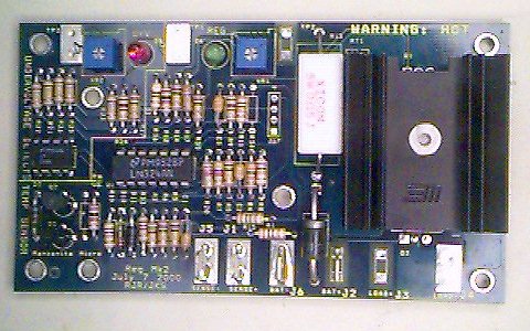
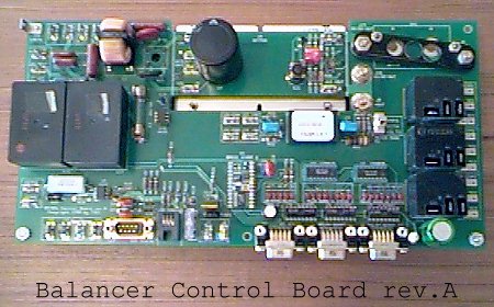
Battery Balancer rev. A
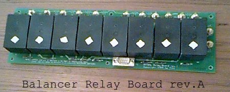
I decided to automate my switch-based system, to take better measurements and experiment with different control strategies. I used relays instead of switches to select each battery. The relays (and safety fuses) are located on relay boards, so they can be mounted as close to the batteries as possible to minimize wiring. Each relay board has 8 sealed relays, to support up to 8 batteries. Up to 3 relay boards can be used, for a total of 24 batteries.
Relays may seem archaic in this 21st century solid-state age, but they are perfect for this application. They have essentially no voltage drop when on, and are a completely open circuit when off. They withstand extremely high voltage spikes, and very high current surges without damage. They tend to fail OFF (not ON like solid-state devices). Life is not a problem due to the slow switching speed.
The rest of the Balancer is on the Control board. I used a Parallax BASIC Stamp 2 for the microcontroller, because it was available, affordable, and easy to program. I'm no programmer, so something that required knowing C, Perl, or Assembly language was out. Plus, this is an R&D tool -- every time I use it, it's likely to be doing something different. I wanted something that was very easy to program, and BASIC fits the bill.
I used a multimeter with an isolated serial output to read the current and voltage of the selected battery. I included a Vicor Batmod DC/DC converter so I could charge any battery at a selected voltage and current. I also included three auxiliary relays, so the Balancer could control various loads for amphour testing and main charger control. More information on Battery Balancer rev.A can be found on Roger Stockton's site at these links:
 Battery
Balancer rev.A documentation:
Battery
Balancer rev.A documentation:
The large rectangular relays can handle battery charge/discharge currents up to 30 amps. While such currents aren't needed for routine balancing, they are useful for high amphour batteries, balancing new batteries, doing amphour capacity tests, and to "prop up" old or weak batteries while driving.
In fact, with this Balancer, range is no longer limited by the weakest battery in the pack. It is instead limited by the average capacity of the batteries in the pack! This is because the Balancer is transferring charge from the highest into the lowest batteries as you drive.
An example: I had this Balancer in my LeCar EV with twelve 12v AGM batteries, and a 22 amp DC/DC converter. The batteries normally provided 40-45 amphours at the 1-hour rate. Everything worked fine for a couple years, so I "just drove it" and didn't pay much attention to what the Balancer was doing. Then one of my batteries began to fail; its capacity slowly fell over the next year. But my EV still operated normally and had normal range. The Balancer was powering its DC/DC converter from the pack as a whole, and using that power to continuously charge the weak battery at 22 amps while driving. Over a 1-hour driving time, that added 22ah to the failing battery's own capacity. I didn't realize anything was wrong until the bad battery's capacity fell below 16ah. At that point, adding 22ah only brought it up to 38ah. This was still weaker than the rest of the pack's 40ah; and so range began to drop.
I replaced that battery, and kept driving. One by one, other batteries failed and were replaced. I eventually got a total of about 22k miles and 10 years life out of that pack, which is exceptionally good for lead-acid AGMs. At the end, about half the batteries had been replaced, and range was down to about 1/4th of what it had been when the batteries were new. But it still worked!
Safety is a key feature of this design. There is a fuse in series with every battery lead in case of relay failures or wiring problems. No possible failure mode in the microcontroller hardware or software can turn on two relays at the same time. Any failure is designed to lead to a fail-safe condition.
I built and sold about a dozen rev.A Battery Balancers. More were built from the bare boards and/or schematics, in either original or modified forms (with different microcontrollers, different relays, different DC/DC converters, etc.)
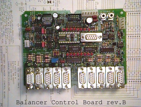
Battery Balancer rev. B
Rev.A was very useful for small packs, and for bench testing batteries. But there were complaints that it was too big, too expensive, and couldn't handle the large numbers of cells found in lithium packs. Over a number of years, I kept improving it and adding features. This has resulted in the current version. Features:
- Handles up to 80 batteries or cells (and more with simple mods).
- Any cell chemistry: Lead-acid, nicad, nimh, or lithium.
- Any cell or module voltage: 1.2v to 12v per module.
- Can monitor, charge, or discharge any cell or battery at up to 30 amps.
- Compact: Only 6" x 4.5" x 3" (about 1/3 the size of rev.A).
- Low Power: 10-15vdc at 10ma from 12v accessory battery.
- Negligible current from cells being monitored. Under 30 microamps during measurements, and ZERO current the rest of the time.
- Low Cost: About half that of the rev.A Balancer.
- On-board isolated precision V-F A/D converters for voltage and current.
- Two additional analog inputs for measuring temperature, etc.
- Optional on-board DC/DC converter.
- RS-232 serial port for display, status, and programming.
- Isolated serial port (EVIbus).
- Isolated digital test input, to sense AC power, pack voltage, etc.
- Four uncommitted control relays with SPDT 240vac/30vdc 15 amp contacts.
- Fail-safe design. Protected against shorts, opens, battery reversals, etc.
- Entirely thru-hole construction, for easy assembly and repair.
- Uses only common, generic, multiple-sourced parts.
Rev.B has divided the large rev.A Balancer board into two smaller boards: A Control board and a Power board. These boards stack to minimize space, and fit inside a standard weatherproof cast aluminum case. The Relay boards have been redesigned to be smaller, use better fuses, and include LED indicators.
The Control board contains the BASIC Stamp 2 microcontroller, isolated A/D converters, relay drivers, LED indicators, serial ports, and a switchmode power supply. There are many versions of the BASIC Stamp 2 with various amounts of speed, memory, and programming features. I use the simplest, least expensive, original one; it has been adequate for my needs, and uses the least amount of 12v power (about 3ma). The isolated A/D converters use LM311 V/F converters, which have very high noise immunity and allow the software to trade off resolution versus conversion time. The relay drivers are fail-safe, and regulate coil current for fast pull-in and then low holding power. The optically isolated EVIbus provides a serial port to communicate with chargers, controllers, and other devices connected to the high voltage pack. A switchmode power supply minimizes the load on the 12v system, and allow even high-power BASIC Stamp 2 versions to be used.
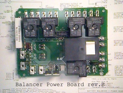
The Power board has relays to switch the DC/DC converter's input between off, precharge, DC pack power, and AC line power. This allows batteries to be balanced with power from the pack itself while driving (shuttling charge between batteries), or with AC power when it is available.
A solid-state relay switches the DC/DC converter's output on/off -- this extends life by switching the Relay board's mechanical relays at zero current (for a life in excess of a million cycles). An optional reversing relay is included to support future lower current (and lower cost) relay boards.
The voltage scaling resistor and current sensing shunt are located on this board. They can be changed for other voltage and current ranges. For example, 0-5v for lithium cells, or 0-18v for 12v lead-acid batteries.
Four uncommitted SPDT 240vac 15amp relays are provided for switching loads unrelated to the Balancer (fans, heaters, external chargers, load resistors for amphour capacity tests, etc.)
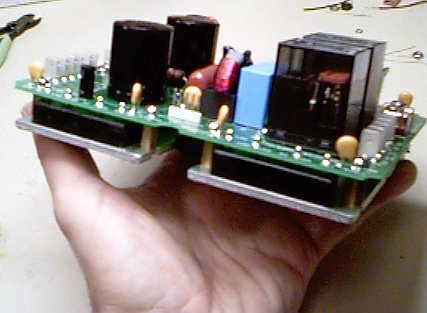
A version of the Power board is also available with sockets for one or two Vicor VI-200 series DC/DC converter modules. These plug into the bottom of the board (see photo at right). VI-200 modules are second-sourced and more common than the Batmod on rev.A, and so are easier to find on the surplus market at lower cost. Most have a 2:1 input voltage range, and the output can be adjusted from 50% to 110% of its nominal value with the on-board trimpot. Choose modules with an input voltage range to match your pack voltage, and an output voltage equal to or higher than your individual cell or battery voltage. The charge voltage is set with the trimpots, and the charge current by the module's internal current limit.
I normally stock the Vicor VI-272-CX/F2, which has a 100-375vdc "universal input", and 15v 5amp output for $50 each. I have a limited stock of VI-200 series modules for other input and output voltages; email me for details and prices.
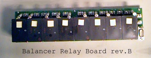
The Relay board has a number of improvements. The fuses were upgraded to high voltage DC types (ABC or 3AB). Connections can be made with screw terminals or 0.25" quick-connects. LEDs indicate which relay is "on". Multiplexing diodes allow multiple boards to be connected to each of the ten relay board outputs (two boards per output supports up to 160 cells, etc.). The board size was reduced to fit inside standard metal or plastic rain gutter downspout (an inexpensive way to make a watertight enclosure).
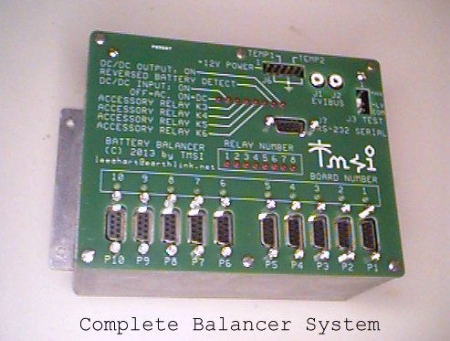
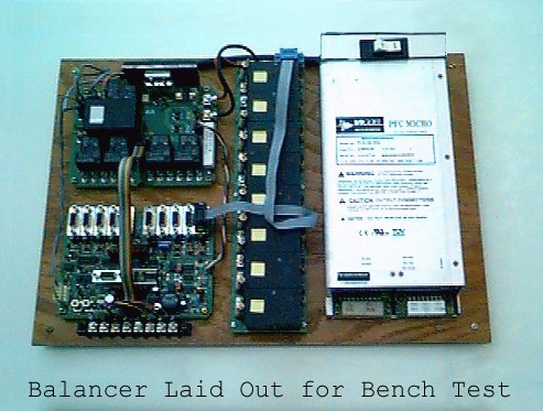
For installation in an EV, the Balancer is normally packaged in a weatherproof cast aluminum enclosure (see the photo at the top of this page). For indoor use, the photo below is my "Bench Test" Battery Balancer system, laid out on a board to make it easy for software development to test boards, and test up to eight cells or batteries on the bench. The DC/DC converter is a Vicor PFC MicroPack, which has a 4:1 input voltage range and three VI-200 series output modules (5v at 30a, 12v at 15a, and 15v at 12.5a, each with trimpots to set the actual voltage). I use the output that best suits the cells or batteries under test at the moment.
Battery Balancer rev.B documentation:
The Battery Balancer continues to be developed and improved. For additional information, parts, prices, and availability, contact me at the address on the HOME page!
Battery Balancer rev.B prices:
- Control board
- $10 -- Bare board, schematic, and parts list
- $99 -- Parts kit; above, with all parts except BASIC Stamp
- $195 -- Assembled and tested, with BASIC Stamp
- Power board
- $10 -- Bare board, schematic, and parts list
- $59 -- Parts kit; above, with all parts
- $99 -- Assembled and tested
- Power board with DC/DC converter
- $30 -- Bare board, schematic, and parts list
- $149 -- Parts kit; above, with all parts except Vicor modules
- $199 -- Assembled and tested, less Vicor modules
- $50 -- Vicor VI-272-CX/F2 module: 100-375v in, 7.5-16.5v out (others available; ask)
- Relay board
- $10 -- Bare board, schematic, and parts list
- $39 -- Parts kit; above, with all parts
- $49 -- Assembled and tested
© 2007-2023 by Lee A. Hart.
Created 3/15/2012. Last update 3/25/2023.
Go to TOP ........
Go to HOME ........
Questions? Comments? Want to help? CONTACT US!
Web hosting provided by Innovative Computers.